This is the poster I presented at the AAG14, trying to summarize my Master’s Thesis project.
Introduction
Modern architecture brought innovative ways to approach the field. New materials, integrated workflows, complex structures, energetics, structural optimization and new shapes, specifically free forms. In such landscape in constant evolution, computational and design tools must keep up the pace as long with designer’s in-depth knowledge of them. The process bringing to construction an architectural idea is long and requires a great amount of variations. Those may be due to the client, the architect, the industry, the engineer and anyone who’s working on it. Not only traditional design methods are running obsolete, but the possibilities arising from having the whole project fully parametrized are becoming more and more compelling. Having the whole project parametrized makes easy to explore all possible solutions and eventually find the best one, using scripts appropriately. This paper presents the workflow necessary to design a free-form roof from scratches and to optimize it. In order to do so, several problems arose which would have been very hard to deal with, without the automatisms inherent to a parametric conception.
The first problem of course, is to draw such a complex surface and the relative structure. As said traditional tools, such as CAD modeling, are not suited enough. Furthermore, it is well known that projects change hundreds of times during their conception and even their realization: updating it with CAD and subsequently with all the software involved (for structural analysis, energetics, fabrication, costs, etc…) is unfeasible.
Those architectures are highly expensive, thus every effort should be conducted to reduce costs. This practice is commonly referred to as optimization, since the aim is optimizing the use of material or the fabrication (both related to costs) to have best results with least expenses. Certain assemblies are expensive beyond imagination or not even possible to realize. In this case, the geometry itself must be modeled to make feasible what otherwise could be unfeasible.
The first problem of course, is to draw such a complex surface and the relative structure. As said traditional tools, such as CAD modeling, are not suited enough. Furthermore, it is well known that projects change hundreds of times during their conception and even their realization: updating it with CAD and subsequently with all the software involved (for structural analysis, energetics, fabrication, costs, etc…) is unfeasible.
For what concerns the project as a whole, the interoperability between softwares is crucial. As aforementioned, in the workflow of free form architectures a lot of softwares find their way in (e.g for structural analysis, energetics, construction phases, cost analysis, drawing). Models must pass seamlessly from one software to the other, without loss of information and within short time. Expanding the concept, the best would be found if the entire project, with all the information it carries, could flow from the first step to the last one without any external input required. The only way do so is by having the whole thing written in a parametric fashion, so that when an input is changed, the whole project updates as long with its various outputs.
The project: between dream and reality
The Scuola Normale Superiore technical division asked to conceive and design a roofing for the Scuola‘s inner courtyard within a framework of accommodating the surrounding area. The courtyard is approximately 20x20m and the highest building is around 22m.
The building is a city landmark situated in the very city center, relevant both for its beauty and its being the pulsing heart of one of the most renowned university in Italy and in the world.
The client was very strict with its requirements. The new structure could not in any way relay on the ancient one and it should leave a certain gap between it and the surrounding roofs for natural air conditioning. Therefore, some kind of vertical structure should have been studied for the glass roofing to stand on, but that new structure should not prevent passers-by to enjoy the surrounding facades.

Several hypothesis have been studied from the architectural point of view and from the structural one. Free form architectures cannot be designed in sequential stages for a change in one aspect will most probably induce a change in one another. Those architectures must be designed in coordination with every professionals working on it and possibly their evolution must follow a loop (see figure on the left)
At last, the best solution was the one shown in the render. The shape resembles a Calla and the beam pattern is composed by intersecting logarithmic spirals. Here one can immediately spot a big difference with traditional gridshells used for roofing. Usually gridshells are found using a relaxation process, thus making the structure working mostly in pure compression. This case is different and was adopted because the client required the structure not to rely on the historical one. Because of this, beams work mainly in bending but by intertwining them the overall stiffness increases and resistance increase too, making the structure redundant.
Several hypothesis have been studied from the architectural point of view and from the structural one. Free form architectures cannot be designed in sequential stages for a change in one aspect will most probably induce a change in one another. Those architectures must be designed in coordination with every professionals working on it and possibly their evolution must follow a loop (see figure on the left)
As already said, traditionally free form roofing can be found by a relaxation procedure. Applying the same procedure in this case would result in a cone-like shape with approximately zero Gaussian curvature. A different approach could be finding the minimal surface joining some given curves, then superimposing those two solutions.
Form finding
As already said, traditionally free form roofing can be found by a relaxation procedure. Applying the same procedure in this case would result in a cone-like shape with approximately zero Gaussian curvature. A different approach could be finding the minimal surface joining some given curves, then superimposing those two solutions.
Minimal surfaces
A minimal surface has the least area respecting a set of boundaries (i.e. curves). Minimal surfaces have several interesting properties such as having zero mean curvature everywhere. Moreover, if we think such surface as being composed of an elastic tensile wrap, in every point the sum of stresses in any direction must be equal to zero or the applied external load if there is any.
Tweaked surface
The eam pattern is derived by intersecting logarithmic spirals projected onto the surface. But there it comes another problem. In fact, fabricability is the key issue for this kind of architecture, with node-torsion being one of its main enemies, therefore the beam pattern must be checked against this issue. It’s known that conical meshes have no node-torsion. Since the beam weaving is made of quads, it could be transformed in a mesh. Once the mesh was found, an optimization procedure was conducted to make it the most conical possible.
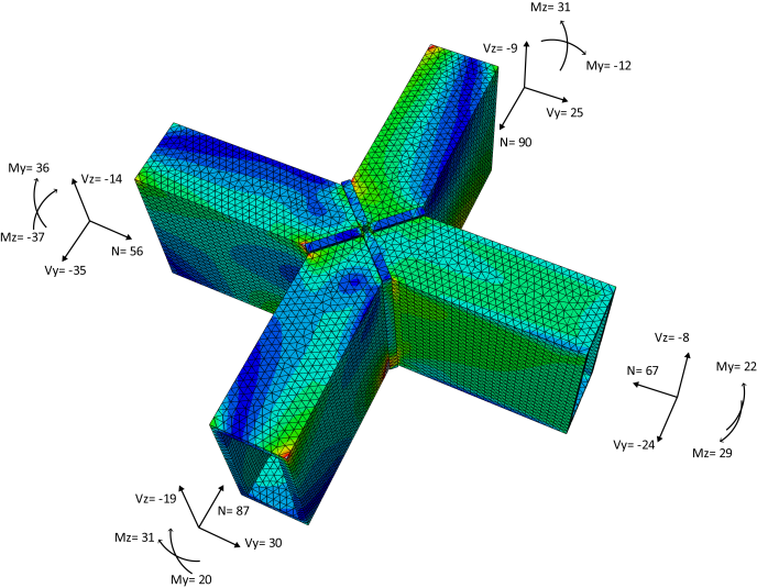
Structural parts of such complex free forms can hardly be dimensioned. In addition, given the high redundancy, an optimization procedure can produce interesting results and in structures with lots of beams a sharp decrease of costs. In this project structural optimization was approached in two ways:
Structural optimization
The former is quite straightforward. A loop tries to optimize beam section’s thickness according to the ratio between load and resistance. The loop runs until a certain threshold is achieved, in this case there were two:
- Loop optimization;
- Evolutionary multi-objective optimization (EMO).
Even though this method not necessarily leads to the best solution possible, EMO does. EMO searches the whole solution domain therefore it is part of the so-called global optimization algorithms.
- The whole structure is verified;
- Displacement and deformations consistent with Eurocodes.
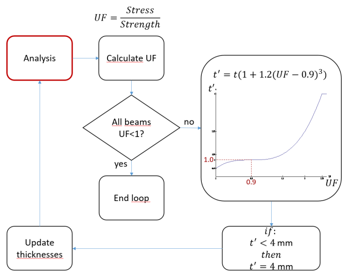
The loop optimization works as follows:
-
- Initially the algorithm analyzes the structure and calculates the ratio between carrying load and resistance (later on referred to as Utilization Factor, UF) for each beam.
- According to the UF the section thickness is updated using the following expression, plotted in the above figure
, where a=1.2 is a parameter to speed up convergence and
is the target Utilization Factor, less than 1.0 to guarantee a certain degree of safety. Basically, when a section is overstressed the algorithm increases its thickness and viceversa. Please note that this process is done using real (float) numbers even if thickness should be an integer, because float numbers produce a better numerical stability than integers.

- The structure is analyzed again using the updated thicknesses and UFs are recalculated. The loop ends when all $UF\leq0.9$ and stiffness requirements are met.
- Once convergence is reached, thicknesses were reduced using the following mapping:
. This is because the above expression does not attempt to reduce overall mass, so this had to be done after. A few beams were no more verified and had to be updated manually. Then, thicknesses that were defined by real numbers had to be rounded up to the nearest integer, actually to the first integer included in a given set of industrial rectangular hollow sections
Panelization
Free forms are not just structure but rather aesthetic. Those shapes need to be covered by panels. This procedure is known as panelization. Glass is possibly one of the most difficult material to use for panelization. There are concurrent necessities in this practice:
- Resemblance with initial shape (position and derivative continuity);
- Cost increases with panel curvature; \item Since each panel is different it requires a specific mold, which are really expensive.
The solution of this problem is not obvious and several papers have been written on that subject (see references at the bottom). Every architecture has its own story and requirements, thus requiring specific adaptation of general concepts such as those presented in the above mentioned papers. In this project panelization has followed two steps:
- Reduction of overall curvature;
- Reduction of the quantity of molds.
Curvature reduction
Even if shape is set, one can attempt to reduce average curvatures by slightly moving the surface control points, thus obtaining an optimized shape very close to the initial one. To do so, a principle of fictitious energy minimization was used:

where 


Mold rationalization
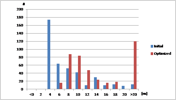
The reduction of the amount of molds is done as follows. First of all, for each panel the two main curvatures are calculated in the middle point. Then, the two lists of main curvature found are merged and divided in sub-lists, each one having the higher curvature value equal to 1.20 times the lowest one. To each sub-list the same mold curvature was assigned, equal to the average curvature in the set. At the end of this procedure, each panel was assigned to a group where every component had the same constant curvature. Then, panels having 

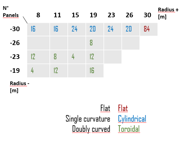
Because of the peculiar shape studied, the panelization was done using three types of mold:
In the following figures the types of molds used are shown and the number of panels they are used for.
- Planar;
- Cylindrical: single curved panels, zero Gaussian curvature;
- Toroidal: double anticlastic curved panels, negative Gaussian curvature;
All the drawings, data, analysis results, are assembled and automatically added to report and graphical visualization. This is crucial to have a clear view on the project phase and to share it with all the professionals working on it. Imagine if every variation, every optimization result should have been drawn by hand or all results data put manually into reports. It would take time for engineers and architects that otherwise would be spent for more productive tasks.
Output data
All the drawings, data, analysis results, are assembled and automatically added to report and graphical visualization. This is crucial to have a clear view on the project phase and to share it with all the professionals working on it. Imagine if every variation, every optimization result should have been drawn by hand or all results data put manually into reports. It would take time for engineers and architects that otherwise would be spent for more productive tasks.
This paper showed the difficulties encountered when designing a free-form architecture and the cutting-edge tools required to deal with it. It’s clear how traditional tools where intermediate steps are not linked to each other, cannot provide a sufficient help to the designer. Moreover, without the full parametrization of the project, it would be impossible to automatically optimize it by having a script screening thousands of different solutions. The procedure here described allowed to greatly reduce costs, especially for what concerns glass panels production, and it was made possible by the increasing use computer engineering is having in the architectural landscape.
Conclusions
- EIGENSATZ, M., DEUSS, M., SCHIFTNER, A., KILIAN, M., MITRA, N. J., POTTMANN, H., AND PAULY, M. 2010. Case studies in cost-optimized paneling of architectural freeform surfaces. In Advances in Architectural Geometry.
- EIGENSATZ, M., KILIAN, M., SCHIFTNER, A., MITRA, N., POTTMANN, H., AND PAULY, M. 2010. Paneling architectural freeform surfaces. ACM Trans. Graphics 29, 3. Proc. SIGGRAPH, to appear
- More videos
References
- EIGENSATZ, M., DEUSS, M., SCHIFTNER, A., KILIAN, M., MITRA, N. J., POTTMANN, H., AND PAULY, M. 2010. Case studies in cost-optimized paneling of architectural freeform surfaces. In Advances in Architectural Geometry.
- EIGENSATZ, M., KILIAN, M., SCHIFTNER, A., MITRA, N., POTTMANN, H., AND PAULY, M. 2010. Paneling architectural freeform surfaces. ACM Trans. Graphics 29, 3. Proc. SIGGRAPH, to appear
- More videos